
Hướng dẫn thay thế van mới cho các thiết bị đang dùng
Bài viết sau đây cung cấp các hướng dẫn từ nhà sản xuất ari valve dành cho các kỹ sư, kỹ thuật viên lắp ráp thiết bị.
Các van mới đã được kiểm tra, niêm phong và đóng gói tại nhà sản xuất. 1 van mới được cung cấp còn nguyên kiện và được kiểm tra trong vòng 6 tháng kể từ ngày lắp đặt. Những van quá 6 tháng kiểm tra phải được thay O-rings và kiểm tra lại.
Quy trình tháo gỡ như sau:
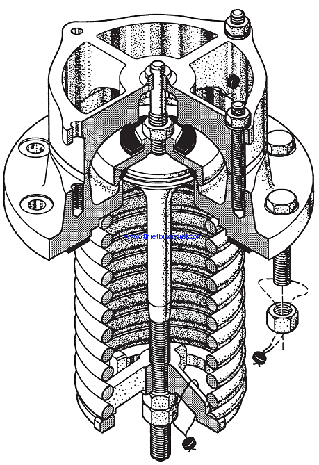
1. Remove the seal wires, items#14.
2. Remove the four nuts securing the top guide, items#17.
3. Lift off the top guide, item#2. It maybe necessary to loosen the guide by tapping with asoft faced hammer.
4. Peel off the bumper washer, item#9.
5. Using two wrenches, one applied to the hex on the retainer, item#6, and the other to the lock nut, item#10, loosen and remove the lock nut.
6. Remove the O-ring retainer with the use of a wheel puller or gently prying under and around the lip with a screwdriver.
7. Use a packing removal pick, remove the O-rings, items #7&8, fromthe retainer taking care not to mar the O-ring grooves.
8. Lay the valve on its side. Using a packing removal pick or a thin blade screwdriver, pry off the gasket. Take care not to mar the sealing surface.
Disassembly of the spring and stem
1. Clean the stem threads with a wire brush and lubricate the threads with a light oil, likeWD-40.
2. Loosen and remove the locknut, item#16. Do NOT remove the spring adjustment nut, item#15, at this time.
3. Measure and record the distance from the end of the stem to the spring adjustment nut. This dimension will be used at reassembly.
4. Place the valve into apress with the spring in the upward position and a mean stop revent the stem from dropping out.
5. Using a press yoke to allow access to the spring adjustment nut, item#15, compress the valve spring to remove all force from the nut. Remove the adjustment nut.
6. Slowly back off the press head until the valve spring, item#4, expands to the relaxed state.
7. Remove the spring follower, item#5.
8. Remove the valve body and stem from the press taking care to prevent the stemfrom
dropping out.
9. Lay the valve body on its side and withdraw the stem.
Hướng dẫn kiểm tra các chi tiết:
Top Stem Guide
The inside of the top stem guide should be free of paint, debris, nicks, burrs or other discontinuities.
Visually in spect the inside of the guide and the mating are a on the upperstem. Any sign of significant wear should be reported to ARI Engineering for review and disposition.
Valve Stem
Remove all scale,residue and other foreign material from the stem with a wire brush. Inspect the stem for signs of corrosion or pitting. Any evidence of corrosion or pitting is grounds for replacement.
The seating surface and O-ring contact areas can be cleaned with 400 grite merycloth. Any discontinuity that would prevent sealing is grounds for replacement. Machining, grinding, welding or other alterations are not permitted.
The stem must be inspected for cracking using either magnetic particle or dyepenetration inspection methods. Cracking is unacceptable. Iffound, the stem must be replaced. Place the stem in ase to fV-blocks and measure straightness with a dial indicator. The stem must be straight within .015TIR. If out of tolerance, the stem must be replaced. Straightening by bending or heat is not permitted.
O-RingRetainer
Clean the O-ring setting surfaces inside the retainer with 400grit emery cloth. Visually inspect the O-ring grooves. They must be free of pits, corrosion or gouges that would prevent proper sealing of theO-rings.
Valve Body
The are a around the valve seat must be free of debris, corrosion and foreign objects. Cleaning can be accomplished with a light brush off blast using glass bead media. The seating surface must be free of nick, burrs and gouges.The area should be cleaned and lightly polished with 400grit emery cloth. Any discontinuity that would prevent the valve from sealing is grounds for replacement. Machining, grinding, welding or other alterations are not permitted. Turn the valve body over to inspect the mounting flange and gasket groove. The gasket groove must be free for residual gasket material, corrosion, nicks, burrs and gouges. Any discontinuity that would prevent sealing is grounds for replacement.
Valve Spring
Remove all scale,residue and other foreign material from the spring with a wire brush. Inspect the spring for signs of corrosion or pitting. If found,the spring must be replaced.The spring must be inspected for cracking using either magnetic particle or dyepenetration inspection methods. Cracking is unacceptable. If found the spring must be replaced. Stand the spring up right on a level surface. Place a straighted ge against the outside and measure for straightness. Turn the spring 90degrees and measure again. The spring must straight within¼”. If out of tolerance, the stem must be replaced. Aluminized springs cannot be inspected with magnetic particle or dyepenetration methods. After cleaning, visually inspect the coating. Any evidence of peeling or flaking of the aluminum is grounds for replacement.
Spring Follower
Remove all scale, residue and other foreign material from the stem with wire brush. Inspect the follower for signs of corrosion or pitting. Any evidence of corrosion or pitting is grounds for replacement. Visually inspect the outside diameter of the follower for signs of significant wear. Wear could bean indication of a bowed spring, misassembled spring or misalignment of the valve with the safety valve nozzle. Any sign of excessive wear should be reported to ARI Engineering for review and disposition.
O-Rings
O-rings must be replaced anytime the retainer is removed from the stem.
Quy trình lắp đặt:
1. With the valve body on its side,insert the stem into the body through the top.
2. Place the valve in the press ensuring the spring is seated in the body and the stem is aligned. Install the spring and spring follower then position the yoke, and compress the spring enough to apply the adjustment nut. With the nut fully engaged, further compress the spring and tighten the nut to the previously recorded dimension from the nut to the end of stem.
3. Release the press and move the valve to the work bench.
4. Install the O-ring sin the O-ring grooves of the O-ring retainer taking care not to tear, stretch or other wise damage the O-rings. Sharp tools should never be used for this operation.
5. Place the retainer with the O-rings on the stem.
6. Install the bumper washer on the retainer.
7. Install the locknut on the stem with a wrench applied to the hex on the retainer and one to the nut. Torque to 50±5ft-lbs
8. Place the top guide over the studs and secure with the 4 nuts.Torque to30±5ft-lbs.
9. Move the valve to the test stand.
10. After testing is complete, install the stem locknut and, using two wrenches, tighten to 50±5ft-lbs.
11. Install newseal wires,items#14.
